Sunday, August 23, 2026

nn20vps: Visual Positioning on a $25 device

I have been experimenting with a fairly simple question:

Can a small, low-cost embedded device work out where a drone is from what its camera sees, without GPS?

That experiment became nn20vps, a proof-of-concept visual positioning system running fully locally on an ESP32-P4.

The goal is not to replace GPS. GPS is more accurate, cheaper in terms of compute, and should obviously be used whenever it is available. The interesting case is what happens when GPS is no longer available.

Could a drone still determine its approximate position well enough to return home or continue along a planned route?

Running the complete VPS on the ESP32-P4

The current implementation runs the complete positioning pipeline on a roughly $25 ESP32-P4 board.

A downward-looking camera image is processed into an embedding and compared with a database of reference imagery. Rather than trusting a single image match, nn20vps combines candidates over time and maintains a position estimate while the aircraft moves.

The complete pipeline includes:

  • image conditioning
  • neural-network embedding
  • vector search
  • temporal tracking
  • cold-start localisation
  • position recovery after a lost track

The embedded vector search is powered by nn20db, my vector database designed for resource-constrained devices.

The system uses two search levels. A fast local search runs around the currently estimated position, while a slower full-map search can search the complete reference database.

The local search handles normal tracking. The full-map search is used for a cold start, recovery after losing the position, and periodic checks to catch a track that has drifted.

That makes a genuine cold start possible: the device can begin without being told its location and search the complete map to find itself.

An 81 km² test area

For the demo I built an approximately 9 × 9 km, or 81 km², reference area around Ghent and Merelbeke in Belgium.

The reference maps come from public orthographic imagery published by Digitaal Vlaanderen.

One thing I specifically wanted to avoid was testing against exactly the same imagery used to create the model and reference database. That would produce impressive results, but would tell me much less about actual visual localisation.

The model and reference database were built using winter 2025 and summer 2021 imagery.

The demo flights use held-out epochs such as winter 2022, winter 2023, winter 2024 and summer 2018.

That means the system has to deal with different foliage, lighting, shadows, vehicles and changes in the landscape rather than simply matching against an identical image.

Current results

On a cross-season test flight running on the ESP32-P4, the system achieved:

  • 55 m median positioning error
  • 183 m p90 positioning error
  • 0.94 Hz camera frame rate
  • recovery from a 1,425 m error down to 28 m

That last number is probably the most interesting one.

The local tracker had drifted far enough that the correct position was outside its search window. The full-map search then searched the complete reference area and successfully re-acquired the aircraft, reducing an error of 1,425 m to 28 m.

For GPS, tens of metres would obviously be poor accuracy.

For a low-cost fallback system whose job is to answer "where am I roughly?" after GPS has disappeared, it starts to become useful.

The simulator

I also built a drone simulator around the system.

The simulator runs on a desktop and provides camera images and simulated telemetry, while the actual VPS runs on the ESP32-P4. Nothing about the positioning system itself is simulated.

The simulator knows the real aircraft position, but the VPS does not. Camera frames are generated from the absolute simulated position, never from the VPS estimate. Otherwise the simulation would become circular and positioning drift could not be tested properly.

The interface therefore shows two positions:

  • the real simulated aircraft position
  • the position reported by the ESP32-P4

It also supports waypoint-to-waypoint flights and lets me introduce disturbances such as wind, compass bias, odometry scale error and visual odometry noise.

What is published

I decided to publish the project as an evaluation/demo kit rather than keep tuning it indefinitely.

The repository contains:

  • the Python drone simulator
  • map download and preparation tools
  • prebuilt ESP32-P4 firmware
  • the nn20db reference database
  • instructions for reproducing the demo

The VPS core itself is written in C and is not published as source at this stage.

The idea is to make the proof of concept easy enough for other people to run and experiment with, and to see whether the approach is interesting before taking it much further.

What is still missing

This is very much a proof of concept.

The current testing uses orthographic map imagery in the simulator. The obvious next validation step is real downward-looking drone footage, ideally around 70 metres altitude, together with real telemetry.

That will introduce additional problems that the simulator does not fully reproduce: lens distortion, vibration, motion blur, camera attitude, altitude errors and a much larger visual difference between the live camera and the reference orthophoto.

That is the test that should show whether the current results translate into something genuinely useful outside the simulator.

For now, though, I think it has reached the point where it is more interesting to let other people try it than to keep polishing the same demo.

Sunday, June 28, 2026

Recent ESP32 Projects: Vector Search, Video Fingerprints and Off-Grid LoRa Text

Over the last months I have been experimenting with a few ESP32 projects around one recurring idea: what can still be done locally, on small and cheap hardware, without depending on a server or cloud service?

This post collects the latest projects: nn20db SDK, a Word2Vec vector-search demo on ESP32-S3, a video fingerprinting demo, and a LoRa / TrailText messaging project.


1. nn20db SDK

nn20db is my small persistent vector-search SDK for Linux and embedded devices. The main idea is to search a database far larger than available memory, directly from persistent storage.

The SDK is aimed at experiments where the index can be built on Linux and then searched on-device, for example on ESP32-S3 or ESP32-P4. It is not meant to beat server vector databases on raw QPS. It is about making useful vector search possible where RAM, CPU and storage are limited.

ESP32-S3 ESP32-P4 HNSW persistent storage offline search

GitHub: https://github.com/brunokeymolen/nn20db-sdk

2. Word2Vec Search on ESP32-S3

This demo uses a Word2Vec index and lets an ESP32-S3 perform nearest-neighbour search locally. The Linux side does the word lookup and vector arithmetic, then sends a single 300-dimensional float32 query vector to the ESP32-S3. The ESP32-S3 searches the index on the SD card and returns the nearest words.

Example queries include simple word lookups and classic vector arithmetic such as: king - man + woman.

GitHub: https://github.com/brunokeymolen/nn20db-word2vec

3. Video Fingerprinting on ESP32-S3

This is a visual demo of local video fingerprinting on an ESP32-S3. The device captures frames from a screen, creates fingerprints, and searches locally to identify the matching video/time.

What I like about this demo is that it makes vector search very tangible: the ESP32 is not just running a toy example, it is matching real visual input against a local database.

4. LoRa Experiments and TrailText

The LoRa project contains two practical ESP32-S3 + SX1262 experiments: a simple Ping-Pong range/radio sanity test, and TrailText, a BLE-to-LoRa text messenger.

TrailText is meant for situations where normal networks are not available. A phone connects to the ESP32 over BLE, the ESP32 handles the LoRa side, and messages are sent to another device.

TrailText banner - text when networks fail

LoRa Ping-Pong

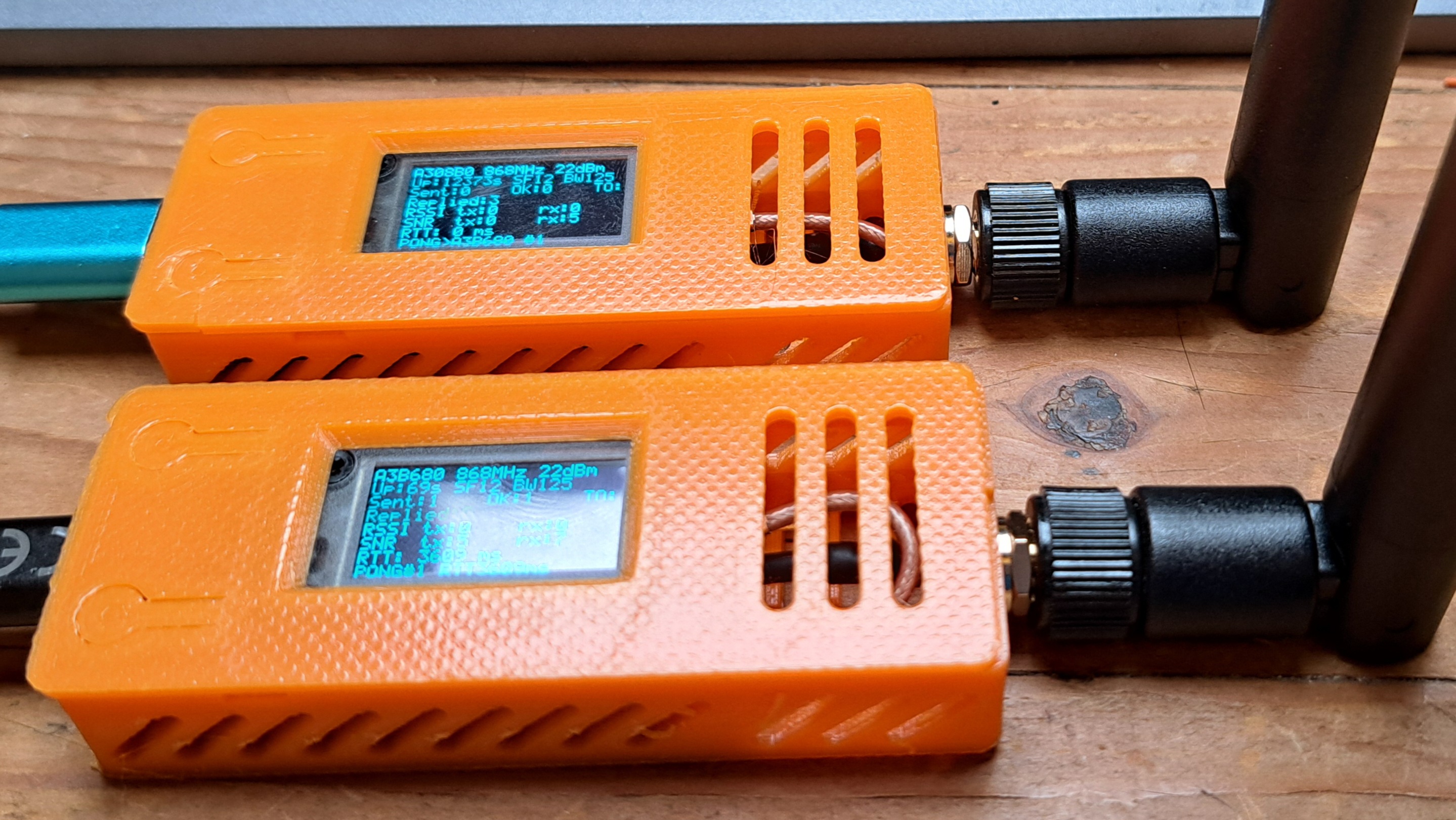
The Ping-Pong firmware is the first thing to flash when testing boards, antennas, frequency, RSSI and SNR. It keeps the radio path simple before moving on to encrypted messaging.

Two Heltec LoRa boards running Ping-Pong firmware

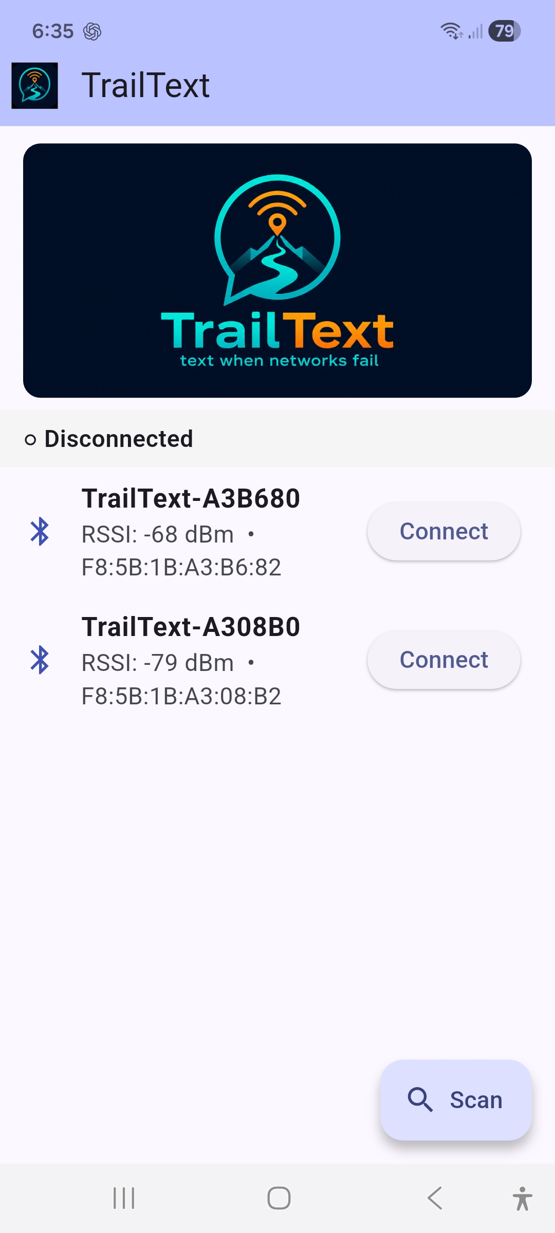
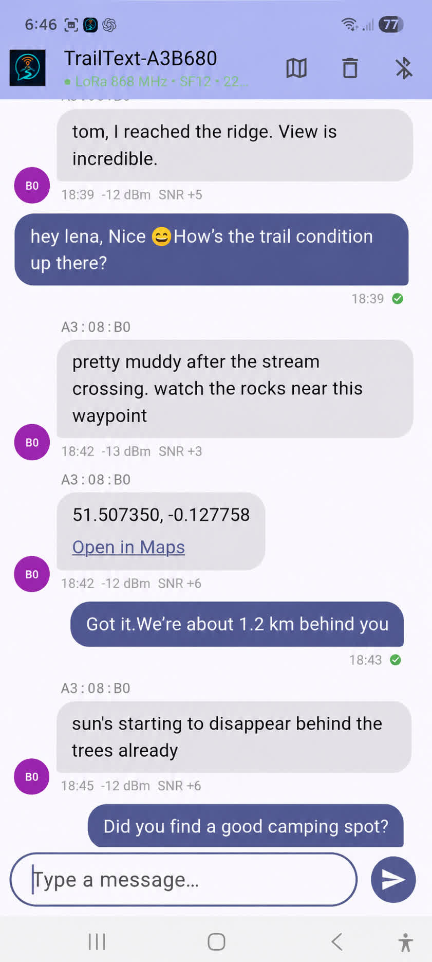
TrailText app screenshots

TrailText start screen ``` TrailText chat screen ```

GitHub: https://github.com/brunokeymolen/lora


What connects these projects?

For me, these are all experiments in the same direction: making small devices do more useful work locally. Sometimes that means searching a large vector index from SD card. Sometimes it means recognizing video frames. Sometimes it means sending text without mobile coverage.

The ESP32 is obviously not a server, and that is exactly what makes these experiments interesting. You have to think about RAM, storage layout, latency, power, radio range and the real limits of the hardware. But when it works, it opens up a lot of fun edge-computing use cases.

More details and source code are available here:

Saturday, February 5, 2022

Commodore 64 Emulator

Terminal UI


Some years ago, out of pure nostalgia and 2 hours of free time a day during the train commute to and from the office, I decided to write a Commodore 64 Emulator. I knew good emulators were available, and it was not my goal to compete with them, but I wanted to get into the details of doing such a task myself.


So I ended up with an emulator that runs the original Kernal and Basic; the UI works in ASCII mode in a Linux Terminal. This allows one to key in and execute Basic code. Please note that many things are not done yet/ever. I consider it a fun hack, and I enjoyed writing it and still enjoy popping up a CBM64 screen from time to time in my Terminal.


The basics of writing an emulator tend to be not that hard, it's a bit of work, though, and since it could be helpful to others, a few components are briefly outlined in this document.


Sources


Core Loop

At the core of the C64, and computers in general, there is a CPU. Simplified, this "Central Processing Unit" does the following steps in a loop.
  • Read an instruction from a memory location
    • the location is given by a variable stored in a two byte register, called the Program Counter (PC)
  • increment the PC
  • Execute that instruction (in an emulator this is basically a unique value that maps to a function), often these are the folowing steps
    • read data (arguments) from memory or from the registers
    • do a computation on that data
    • write the result to registers or memory
  • start all over again

The full list of instructions, called Opcodes, can be found in the file  MOS6510.cpp.


Memory

Below is an overview of the CBM64 memory map.


The the memory range is from 0x0000 to 0xFFFF, not surprising this fits into 2 bytes.
Note that this is not all just RAM. Like the kernal ROM is (by default) mapped at address 0xF000 - 0xFFFF, the Basic at 0xA0000 - 0XC0000. The Screen, which is pretty usefull to communicate with the computer users is mapped at 0x0400 - 0x0800, that means if we instruct the CPU to write an output of an instruction to 0x0400, likely something will be shown on screen (for example try: POKE 1024, 49). The screen output is handled by a chip called VIC and my implementation does just the basics, being ASCII mode.


Design 

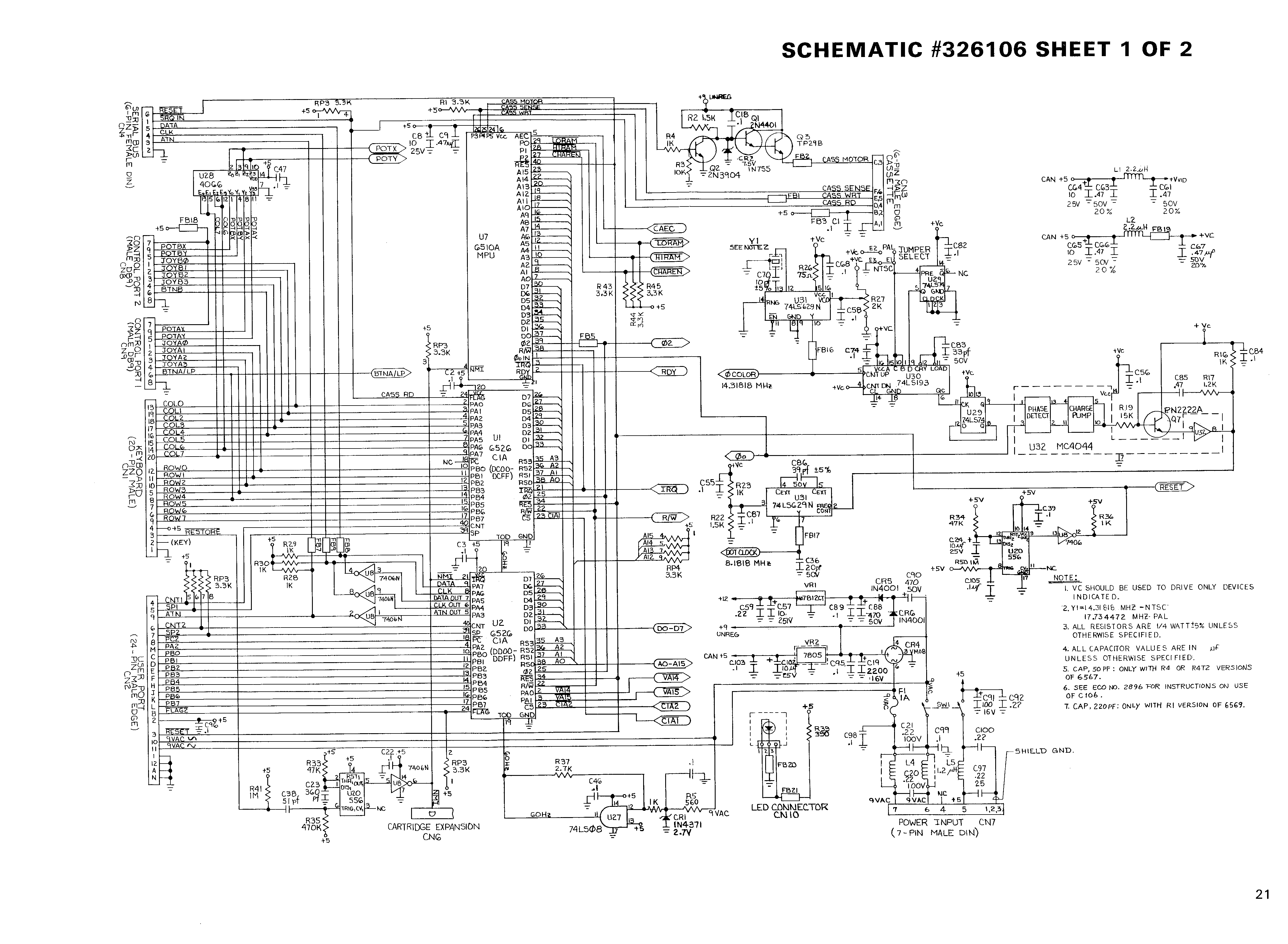
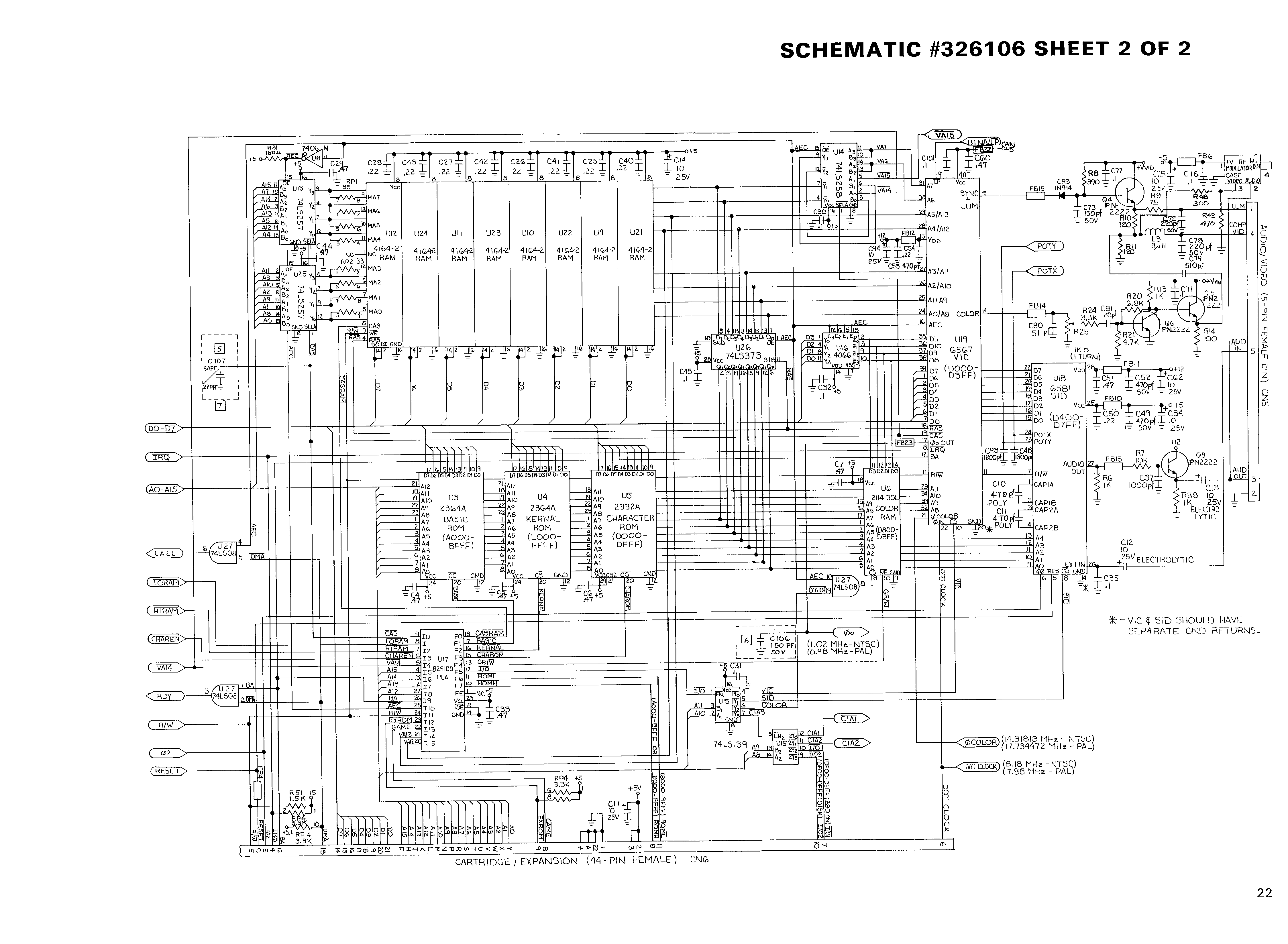
These are two nice schemas of the Commodore 64 Internals:


http://www.zimmers.net/anonftp/pub/cbm/schematics/computers/c64/326106-1of2.gif

http://www.zimmers.net/anonftp/pub/cbm/schematics/computers/c64/326106-2of2.gif


You will notice the following components

  • 6510 CPU
  • 6567 VIC (NTSC Video Interface Chip; can be 6569 for PAL) 
  • 6581 SID (Sound Interface Chip)
  • 8 x 4164-2 RAM (each 65.536 x 1 bit, so 8 make the 65.636 Bytes Ram)
  • Color RAM
  • Kernal ROM
  • Basic ROM
  • Character ROM
  • Bus
  • 6526 CIA's for IO Stuff

To get a CBM 64 running, you need to implement the 6510 CPU, at least the Text mode VIC, RAM and some IO for keyboard input and basic IRQ handling. Once done you should only need to load the ROM's, like the Kernal (yup, it was a Kernal at that time, the 'a' is not a typo) at the right place in memory, set the program counter to a start location and start the CPU.

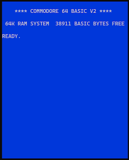
If all go's right, the emulator should start the Kernal and the Basic and the well known "38911 Basic Bytes Free" should appear.


Implementation overview

Memory - Bus

Memory reads and writes are done over a BUS.

Implementing Memory could be as easy as defining an array of bytes. However, because devices and ROM are mapped into the address space, it is useful to make a class that allows registering memory mapped devices and an interface to read and write memory.

I implemented it in a Class called Bus.cpp , all memory reads and writes are done via the Bus and this one knows about all devices that are  mapped in the address space. It will make sure a reads and writes are done to and from whatever is mapped at a given address. 

The following devices are registered in the Bus, note I only mapped one CIA where there are actually 2. One was enough to get the ASCI mode running.
  24   mBus = CBus::GetInstance();  
  25   mVic = new CMOS6569();  
  26   mRam = new CRam();  
  27   mBasicRom = new CBasicRom();  
  28   mKernalRom = new CKernalRom();  
  29   mProcessor = new CMOS6510(mMutex);  
  30   mCia1 = new CMOS6526A(mMutex);  
  31   mCharRom = new CCharRom();  

RAM

Implemted in : Ram.cpp
RAM is just a buffer of bytes, registered to the BUS from 0x0000 - 0xFFFF, if nothing else is mapped o n the given address reads and writes (peek and poke) will happen on this buffer.

ROM

There are 3 ROM's in the implementation
The idea here is, since it is just data and they are mapped as memory, to just provide Reads from it. In CBM64 terms; Peek. And that is what the implementations do.


CPU, the 6510

Here most magic happens, this is the code that reads Instructions (opcodes) and execute the necessary steps for that instruction.

There are two matrixes in this class, one with all opcodes organized per address mode.
Another one holds the CPU cycles spent by the 6510 to execute the instruction. Some instructions take extra cycles for certain address modes, these are counted in the instuctions implementation. Like the BRANCH instructions take an extra cycle if the branch is executed, and another extra cycle if the address to branch too crosses a page boundary (this is partially done in this implementation).

The main function in this class is 'Cycle()'. This reads and executes a next instruction and runs the IRQ if needed. 

Boot

At start the PC (Program Counter) is set to an address specified at the Kernal address 0FFFC.  

r_pc  = mMemory->Peek16(0xFFFC); 

The CPU starts reading and executing insructions from that address.


CPU Cycles

The PAL version of the CBM64 CPU runs at 985 KHz and the NTSC at 1023 KHz. 

The MOS6510.cpp implementation has a Cycle() method, this method fetches and executes one instruction (it also runs the IRQ's if needed). Just running Cycle() in an endless loop would run the processor but because our modern CPU's are fast, and even taken into account the overhead of the not so optimal implementation of the 6510 emulated instructions, it wil largely overshoot the intended 1023KHz.

To solve this the Cycle() method returns the number of 6510 CPU cycles used by the instructions executed. A way to implement a somewhat accurate CPU cycle rate is to count the spent CPU cycles up to 1.023.000 (or larger), check the actual time spent, and sleep the remainder of the second, then carry over the rest of the1.023.000 cycles to the next round. This is implemented in main.cpp, actually it does it a bit more grannular and checks intervals of 100ms instead of 1 second. One can make it run at smaller intervals as needed.


Monday, April 27, 2020

YOLOv3 Inference Server for Intel Movidius


In a previous post, I went over the steps to get the "Intel Neural Compute Stick 2" working on a Raspberry Pi. It handles the conversion of the Darknet YOLOv3 model, trained on a COCO dataset, to OpenVINO IR format.


As a demonstration of that, I made a small Pyhton Flask web service that is suitable to run on the Raspberry Pi. Using a basic web UI you can PUSH images to it to do object detection and classification. 

While processing some validation images from the COCO dataset, the observed inference speed is about 400ms, do add another 150 ms to post-process the results. This makes about 550 ms for the full object detection, which sounds pretty acceptable to me. Given it runs on a Raspberry Pi4 and I made the postprocessing code to be readable, not to have optimal performance. 

The full source code is available for download on github 
https://github.com/brunokeymolen/movidius-inference-server


Sunday, April 26, 2020

Run YOLOv3 on Raspberry Pi with the Intel Neural Compute Stick 2

While working on a personal project I decided to run YOLOv3 on a Raspberry Pi. I mean the full YoloV3, not the tiny version. Given the availability of decent tutorials on the internet, it did not take too long to get things working. And as expected, the inference results were great but, considering the 12 seconds to do so, it became clear that the Pi (3B+) was never designed for such tasks.


As a solution, I added VPU power (Vision Processing Unit) in the form of an Intel Neural Compute Stick 2, for some also known as Intel Movidius, or just NCS2. This is a less than 100$ USB compute stick solely made for Neural Network inference.


In order to use the Intel Movidius, you need to install the necessary software on the Raspberry Pi. And before running a Neural Network model it needs to be converted to an 'Intermediate Representation' (IR) format. This post handles the necessary steps to do the software installation, to convert the Darknet YOLOv3 model to IR, and to run a demonstration on the Raspberry Pi.

The document is split into the following sections:
  • Install Raspberry Pi Buster
  • Install OpenVINO
  • Prepare a Docker image for conversion to IR
  • Convert to IR
  • Run YOLOv3 Demo on the Raspberry Pi with camera input

Conventions used in this document:


pi$ : shell commands to be given at the Raspberry Pi
linux$ : shell commands to be given at a Linux machine (Ubuntu in my case)
docker$ : shell commands to be given at a docker container

Install Raspberry Pi Buster

Insert a new Raspberry Pi SD card in your Linux machine and check the device name. The following commands are useful for this:

linux$ sudo fdisk -l
linux$ lsblk


(the SD is sde in the example, but possibly you have another one, make sure to change that to not accidentally overwrite your data)

Download Rasbian Buster-lite at: 
(buster-lite is fine)

Unzip the downloaded file and put the Buster image to the Raspberry Pi SD card:

linux$ sudo dd if=2020-02-13-raspbian-buster-lite.img of=/dev/sd[e] status=progress bs=4M

SSH.
Create a file ‘ssh’ on the boot partition to enable SSH

lsblk
sde      8:64   1  29.7G  0 disk 
├─sde1   8:65   1   256M  0 part 
└─sde2   8:66   1   1.5G  0 part 

linux$ sudo mkdir /mnt/sd
linux$ sudo mount /dev/sde1 /mnt/sd
linux$ sudo touch /mnt/sd/ssh
linux$ sudo umount /mnt/sd

Put the SD card in the Pi and start it up.
Figure out the IP address and login over SSH

ssh pi@<ip address of Pi> 

username: pi
password: raspberry

One of the first things to do is to make the full capacity of the SD card available, do that as follow:

pi$ sudo raspi-config 

Choose : Advanced Options -> Expand Filesystem ….

Install the next software:
pi$ sudo apt-get update
pi$ sudo apt-get install git
pi$ sudo apt-get install cmake
pi$ sudo apt-get install libatlas-base-dev
pi$ sudo apt-get install python3-pip
pi$ sudo apt install libgtk-3-dev

pi$ pip3 install --upgrade pip
pi$ pip3 install numpy

Install OpenVINO

OpenVINO is an Intel toolkit that contains a copy of OpenCV and has the necessary drivers and tools to manage models and run them on the Intel Movidius. There is a runtime version for Raspberry Pi, follow the installation steps below. They are based on the following document: https://docs.openvinotoolkit.org/latest/_docs_install_guides_installing_openvino_raspbian.html


At the Raspberry Pi, do:
pi$ mkdir -p ~/projects/openvino
pi$ cd ~/projects/openvino
pi$ wget https://download.01.org/opencv/2020/openvinotoolkit/2020.1/l_openvino_toolkit_runtime_raspbian_p_2020.1.023.tgz

Untar the download:
pi$ tar -xzvf l_openvino_toolkit_runtime_raspbian_p_2020.1.023.tgz


Make the OpenVINO environment to initialize at the start of the Pi:

pi$ echo "source /home/pi/projects/openvino/l_openvino_toolkit_runtime_raspbian_p_2020.1.023/bin/setupvars.sh" >> ~/.bashrc
pi$ source ~/.bashrc 

[setupvars.sh] OpenVINO environment initialized


Finally add the USB rules:

pi$ sudo usermod -a -G users "$(whoami)"
pi$ sh ~/projects/openvino/l_openvino_toolkit_runtime_raspbian_p_2020.1.023/install_dependencies/install_NCS_udev_rules.sh

At this point, the NSC2 should work and I advise to test it before continuing:

Plug-in the Intel Movidius USB stick in the Pi, create a file "openvino_fd_myriad.py" and add the code below (as explained in “Run Inference of Face Detection Model Using OpenCV* API” at


import cv2 as cv

# Load the model.
net = cv.dnn_DetectionModel('face-detection-adas-0001.xml',
                            'face-detection-adas-0001.bin')

# Specify target device.
net.setPreferableTarget(cv.dnn.DNN_TARGET_MYRIAD)
# Read an image.
frame = cv.imread('face.jpg')
if frame is None:
    raise Exception('Image not found!')
# Perform an inference.
_, confidences, boxes = net.detect(frame, confThreshold=0.5)
# Draw detected faces on the frame.
for confidence, box in zip(list(confidences), boxes):
    cv.rectangle(frame, box, color=(0, 255, 0), thickness=3)
# Save the frame to an image file.
cv.imwrite('out.jpg', frame)

Make sure to download the following pre-trained Face Detection model instead of the one mentioned in the above document:

$ pi$ wget https://download.01.org/opencv/2019/open_model_zoo/R3/20190905_163000_models_bin/face-detection-adas-0001/FP32/face-detection-adas-0001.xml
$ pi$ wget https://download.01.org/opencv/2019/open_model_zoo/R3/20190905_163000_models_bin/face-detection-adas-0001/FP32/face-detection-adas-0001.bin


  • Upload a photo to the Pi, name it face.jpg
  • run the face detection code "pi$ python3 openvino_fd_myriad.py

If all works, the outcome (out.jpg) should be something like this:


Prepare a Docker image for conversion to IR

Converting a model to the OpenVINO Intermediate Representation (IR) needs to be done with a full OpenVINO-toolkit installation, and thus, not at the Raspberry Pi which has only a runtime version. In this post I use an Ubuntu Linux machine, it should work on Mac OS and Windows but the steps may differ.

To make things more manageable, and to not mess up your current Linux installation, I created a Dockerfile to do the conversion. It contains all the necessary components to convert. 


linux$ mkdir ~/projects
linux$ cd ~/projects
linux$ git clone https://github.com/brunokeymolen/devops.git
linux$ cd ~/projects/devops/docker-images/openvino-movidius


Download a full OpenVINO toolkit from the following link and put it next to the Dockerfile:


linux$:~/projects/devops/docker-images/openvino-movidius(master)$ ls -lGg
total 496316
-rw-r--r-- 1      2766 Apr 12 15:02 Dockerfile
-rw-r--r-- 1 508213676 Apr  5 11:04 l_openvino_toolkit_p_2020.1.023.tgz
-rw-r--r-- 1       431 Apr  6 20:07 README


Open the Dockerfile and, if needed, change:
ARG OPENVINO_TOOLKIT_NAME=l_openvino_toolkit_p_2020.1.023.tgz


Build the Docker image:
linux$ docker build -t openvino-movidius .

If all is fine the image should be something like this:
linux$ docker image ls | grep openvino-movidius
openvino-movidius            latest              89b2c076f373        2 weeks ago         3.86GB

Get the YOLOv3 scripts to convert the weights.

First, on the Linux host, download YOLOv3 (choose whether you want yolov3 or yolov3-tiny)

Because it is needed only temporarily, I installed it at the /tmp directory, adapt the location if you want.


linux$ mkdir /tmp/openvino
linux$ cd /tmp/openvino
linux$ git clone https://github.com/mystic123/tensorflow-yolo-v3.git
linux$ cd tensorflow-yolo-v3
linux$ git checkout ed60b90


Get the coco class names and download the model weights to the same directory:
linux$ wget https://raw.githubusercontent.com/pjreddie/darknet/master/data/coco.names
linux$ wget https://pjreddie.com/media/files/yolov3.weights
linux$ wget https://pjreddie.com/media/files/yolov3-tiny.weights

The result should be similar to this:
linux$ :/tmp/openvino/tensorflow-yolo-v3((HEAD detached at ed60b90))$ ls -lGg
total 276868
-rw-r--r-- 1       625 Apr 26 09:32 coco.names
-rw-r--r-- 1      3219 Apr 26 09:30 CODE_OF_CONDUCT.md
-rw-r--r-- 1      1552 Apr 26 09:30 convert_weights_pb.py
-rw-r--r-- 1      1474 Apr 26 09:30 convert_weights.py
-rw-r--r-- 1      3225 Apr 26 09:30 demo.py
-rw-r--r-- 1     11357 Apr 26 09:30 LICENSE
-rw-r--r-- 1      2335 Apr 26 09:30 README.md
-rw-r--r-- 1     10595 Apr 26 09:30 utils.py
-rw-r--r-- 1      9306 Apr 26 09:30 yolo_v3.py
-rw-r--r-- 1      4030 Apr 26 09:30 yolo_v3_tiny.py
-rw-r--r-- 1  35434956 Apr 26 09:33 yolov3-tiny.weights
-rw-r--r-- 1 248007048 Apr 26 09:32 yolov3.weights


Run (and share the /tmp/openvino directory)
linux$ docker run -ti --device-cgroup-rule='c 189:* rmw' -v /dev/bus/usb:/dev/bus/usb -v /tmp/openvino:/mnt/host openvino-movidius


Convert to IR

There are two steps in the conversion to IR.
  • convert the yolo weight file to .pb file
  • convert the .pb file to IR

Convert the Yolo weight file to .pb file
This step uses the scripts from the tensorflow-yolo-v3.git repository, which is on the /tmp directory on the Linux Host but needs to be executed from within the docker image, we use the shared directory for that.

docker$ cd /mnt/host/tensorflow-yolo-v3/
docker$ python3 convert_weights_pb.py --class_names coco.names --data_format NHWC --weights_file yolov3.weights

In case you need Yolov3-tiny:
docker$ python3 convert_weights_pb.py --class_names coco.names --data_format NHWC --weights_file yolov3-tiny.weights --tiny

You will notice a bunch of warnings but at the end, the following message appears:
1186 ops written to frozen_darknet_yolov3_model.pb.

Check if the .pb file is created:
docker$:/mnt/host/tensorflow-yolo-v3# ls -lGg | grep frozen_darknet_yolov3_model.pb
-rw-r--r-- 1 248192514 Apr 26 07:45 frozen_darknet_yolov3_model.pb

Convert the .pb file to IR

docker$ cd /opt/intel/openvino_2020.1.023/deployment_tools/model_optimizer 
docker$ export MO_ROOT=`pwd`

YOLOv3:
docker$ python3 mo_tf.py --input_model /mnt/host/tensorflow-yolo-v3/frozen_darknet_yolov3_model.pb --tensorflow_use_custom_operations_config $MO_ROOT/extensions/front/tf/yolo_v3.json --batch 1 --generate_deprecated_IR_V7

YOLOv3-tiny:
docker$ python3 mo_tf.py --input_model /mnt/host/tensorflow-yolo-v3/frozen_darknet_yolov3_tiny_model.pb --tensorflow_use_custom_operations_config $MO_ROOT/extensions/front/tf/yolo_v3_tiny.json --batch 1 --generate_deprecated_IR_V7

The result is the YOLOv3 model in IR format.
docker$  ls -lGg
...
-rw-r--r-- 1 247691380 Apr 26 07:55 frozen_darknet_yolov3_model.bin
-rw-r--r-- 1     29847 Apr 26 07:55 frozen_darknet_yolov3_model.mapping
-rw-r--r-- 1    108182 Apr 26 07:55 frozen_darknet_yolov3_model.xml
...


Copy them to the host and scp them to the Raspberry Pi.

docker$ cp frozen_darknet_yolov3_model.bin /mnt/host/tensorflow-yolo-v3/.
docker$ cp frozen_darknet_yolov3_model.xml /mnt/host/tensorflow-yolo-v3/.

pi$ mkdir ~/models

linux$ cd /tmp/openvino/tensorflow-yolo-v3
linux$ scp frozen_darknet_yolov3_model.xml pi@<ip address>:~/models/.
linux$ scp frozen_darknet_yolov3_model.bin pi@<ip address>:~/models/.
linux$ scp coco.names  pi@<ip address>:~/models/.

Run YOLOv3 Demo on the Raspberry Pi with camera input

In this step, we use the previously converted Darknet YOLOv3 model.


OpenCV has the following object detection demo:

At the Raspberry Pi:
pi$ mkdir ~/yolov3demo
pi$ cd ~/yolov3demo
pi$ wget https://raw.githubusercontent.com/opencv/open_model_zoo/master/demos/python_demos/object_detection_demo_yolov3_async/object_detection_demo_yolov3_async.py

The code has video output, so if you connect over ssh, login as follow: 
linux$ ssh pi@<ip address> -Y

you might need to install X on the Pi for the ssh -Y option, I did that by installing xterm (that pulls all necessary libraries):
pi$ sudo apt install xterm


If a camera is attached to the Raspberry Pi:
pi$ cd ~/yolodemo
pi$ python3 object_detection_demo_yolov3_async.py -m ~/models/frozen_darknet_yolov3_model.xml --labels ~/models/coco.names -d MYRIAD -i cam -pc


Inference Server
If you don't have a camera, no worries, please check my next post. I'll explain how to turn your Raspberry Pi, with Intel Movidius, into an Inference server accessible over a web interface.